Keywords
INTRODUCTION
Heart failure is one of the most important of all public health problems; it is the third cause of death due to cardiovascular disease in developed countries, a significant cause of morbidity, and is associated with a large hospital burden.1,2 Cardiac resynchronization therapy (CRT) is an appropriate therapeutic option for patients with heart failure, and is associated with a reduction in heart failure-related and overall morbidity and mortality.3-8 In 2005, both European and American clinical practice guidelines accepted biventricular stimulation as a class I indication (evidence level A) in patients with a New York Heart Association functional class of III-IV in the presence of left ventricular dysfunction and QRS prolongation.9,10 However, the benefits of this therapy do not depend solely on careful patient selection but also on the position of the electrodes, particularly of that which must stimulate the left ventricle (LV).11-13 In agreement with the existing information, the ideal location of the latter electrode is the lateral region since this shows the greatest delay in contraction in the presence of left bundle block.14,15
The results of large clinical trials indicate that intravenous implantation of the LV electrode is successful in 90% of attempts, with the electrode being positioned in the optimum position in some 64%-79% of patients.4,6,7,16 Unfortunately, implanting the electrode in a coronary vein can be difficult in up to 20% of patients, a consequence of unfavorable anatomical factors.17-19 Detailed knowledge of the patient's coronary venous anatomy is therefore essential for an appropriate vein to be selected and for any obstacles that might hinder the implantation procedure to be detected.
The present study examines the usefulness of hyperemic venous return angiography for determining the coronary venous anatomy of patients, comparing this technique with occlusive retrograde venography (the technique currently employed at most centers).20 The studied technique takes advantage of the coronary angiography procedure commonly indicated in the assessment of candidates for CRT, allowing the planning of the implantation procedure without significant further costs or increasing morbidity.
METHODS
The original study population included 221 patients who received a CRT device at the Hospital Universitario de Gran Canaria Dr Negrín. For 200 of these, coronary angiography was indicated prior to implantation. The coronary venous anatomy of the latter patients was studied by hyperemic venous return angiography and occlusive retrograde venography.21 All patients gave their informed consent to undergo both procedures. Table 1 shows the characteristics of these patients.

Analyses were made of the segment between the coronary sinus ostium (CSO) and the anterior interventricular vein, classifying the visibility of the coronary veins on the 0-3 point scale described by Muhlenbruch et al22 (Table 2).

Angiography of the coronary venous system (projections: 30º anterior left oblique, anteroposterior, and 30º anterior right oblique) was performed using a non-ionic, low osmolality iodide contrast medium. All findings were recorded in digital format and analyzed independently by 2 experienced observers.
Hyperemic Venous Return Angiography
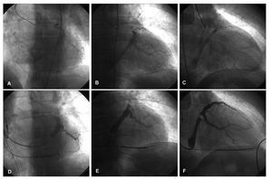
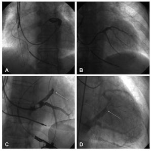
The left coronary artery was catheterized with a Judkins®6F catheter (Cordis Corp., Miami, Florida) and 200 µg of intracoronary nitroglycerine or 60 µg of adenosine were administered to increase the coronary flow and, therefore, the venous return. Some 6-10 mL of contrast medium were then injected. Filming took place over 5-10 s in order to observe the venous phase of the coronary tree (Figures 1A-C).

Figure 1. Hyperemic venous return angiography (A: ALO 30°. B: AP. C: ARO 30°) and occlusive retrograde venography (D: ALO 30°. E: AP. F: ARO 30°) performed on the same patient.
Occlusive Retrograde Venography
After reaching the coronary sinus (CS) with the guidewire, a balloon catheter was introduced; this was positioned half way between the posterior and anterior interventricular veins. After inflating the balloon and checking that occlusion was complete, 5 mL of contrast medium were injected, leading to the opacification of the distal portion of the coronary venous system. The proximal portion was also made opaque via the intervenous connections—when present21 (Figure 1DF). When not present, angiography at the level of the CSO was undertaken with the balloon inflated. On those occasions when the AIV was not adequately visualized, an extra injection of contrast medium was made with the balloon in a more advanced position.
Terminology
The terminology used for the CS and its tributaries was that described by von Lüdinghausen23:
- Anterior interventricular vein (AIV): this runs along the anterior interventricular groove until it reaches the atrioventricular groove
- Great cardiac vein (GCV): this arises as a continuation of the AIV and runs parallel to the circumflex vein to drain the CS, normally at the level of the obtuse border
- Coronary sinus (CS): this arises as a continuation of the GCV. At its point of origin in receives input from the oblique vein of Marshall. At the end of its trajectory it opens into the right atrium via the CSO
- Middle cardiac vein (MCV): this is also known as the posterior interventricular vein since it runs along the groove of the same name, normally ending near the CSO
- Posterior and lateral veins: these provide the venous drainage of the free wall of the LV and end at the CS and GCV respectively
Statistical Analysis
Quantitative variables were described in terms of their arithmetic means and standard deviations. Nominal qualitative variables were analyzed by determining the absolute frequency of the appearance of each category as well as the relative and ordinal frequencies, via the medians and 25th and 75th percentiles.
The association between the opacification caused by the balloon-induced occlusion and the existence of intervenous connections was analyzed using the c2 test. The Wilcoxon test for paired samples was used to compare the visualizations obtained with both techniques. Differences in the anatomical information thus provided were analyzed using the McNemar test.
RESULTS
Inter- and intraobserver variability was examined and the agreement found to be 93% and 98% respectively.
Overall, adequate anatomical information was collected from 99.5% of all patients; the CS and GCV were visible in all patients. Appropriate opacification of the MCV and AIV was achieved in 96% and 92.5% of patients respectively. The lateral vein was optimally visualized in all patients. No patient had to be excluded due to suboptimal opacification of the coronary venous anatomy.
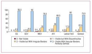
To visualize the venous system by hyperemic venous return angiography, a total of 17.8 (1) (median, 18; range, 12-18) mL of contrast were injected in the 3 projections. This outlined the venous anatomy in a fashion appropriate for analysis in 98% of patients. The CS and GCV became opaque in 100% and 99.5% of patients respectively (Figure 2). The MCV and AIV were optimally visualized in 96% and 94.5%, of patients respectively. Finally, the veins of the lateral region of the LV were made adequately visible in 97.5% of patients, and in a discontinuous fashion in the remaining 2.5%. No complications were encountered with this technique.

Figure 2. Visibility of each vessel with hyperemic venous return angiography (in percentages).
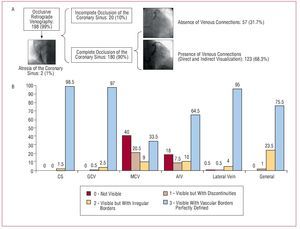
The cannulation of the CS for occlusive retrograde venography was possible in 198 (99%) patients, but failed in 2 patients due to atresia of the CSO. The occlusion of the CS achieved with the balloon was complete in 180 patients (90%). In 123 patients (61.5%), the presence of intervenous communications allowed the complete opacification of the coronary venous system (either directly or indirectly); in the remaining 38.5% of patients extra injections of contrast medium were required with the balloon inflated close to the CSO for the anatomy of this region to be properly seen (Figure 3A). In this fashion, retrograde venography with the aid of the balloon allowed the visualization of the CS and GCV in 100% and 99.5% of patients respectively (Figure 3B). The MCV could only be seen indirectly via intervenous connections (42%). In those patients in whom the balloon did not provide complete occlusion, the opacification of the MCV was poorer (P=.025), as it was in those patients without intervenous connections that could provide a flow of contrast medium to the regions proximal to the occluding balloon (P<.001). In those patients in which both the latter conditions were present (ie, complete occlusion by the balloon and the presence of collateral connections), better opacification of the vessel was obtained than in all other patients (P<.001). The AIV was adequately visualized in 75% of patients but this was not possible in 25%, despite the achievement of complete occlusion with the balloon. As for the MCV, incomplete occlusion of the CS was significantly associated with inadequate opacification of the AIV (P<.001). Finally, the lateral vein was adequately visible in 99% of patients. The total quantity of contrast medium injected for the analysis of the coronary venous system when using this technique was 18.26 (4.1) (median, 18; range, 8-32) mL, in a total of 3.7 (0.9) (median, 3; range, 2-6) injections. In 93 (46.5%) patients it was necessary to use additional injections with the balloon in a more distal and/or proximal position for the complete coronary venous system to be seen. Four patients (2%) suffered dissection of the GCV and the appearance of a contrast tattoo during the injection of the contrast medium, but in no case did this impede the implantation of the venous electrode, nor did echocardiography performed at the end of the procedure detect pericardial hemorrhage.

Figure 3. A: schematic representation of the patients studied by occlusive retrograde venography. B: visibility of each vessel in occlusive retrograde venography (in percentages). AIV: anterior interventricular vein; CS: coronary sinus; GCV: great cardiac vein; MCV: middle cardiac vein.
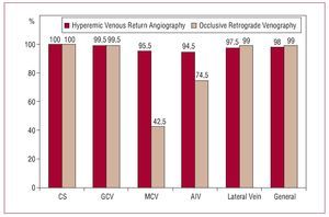
Although in general there were no significant differences in the opacification of the coronary venous system, the visibility scores obtained with occlusive retrograde venography were slightly higher than with the venous return phase with respect to the CS and the veins of the lateral region of the LV (P=.034 and P<.001, respectively). However, the anatomical information provided was adequate (2 or 3 points on the Muhlenbruch scale) in 100% and 97.5% of patients respectively (Figure 4). In contrast, the MCV and AIV were visualized in more detail when hyperemic venous return angiography was used (P<.001 in both cases), although inflation of the balloon in a more distal position during retrograde venography allowed adequate opacification of the AIV.

Figure 4. Comparison of adequate opacification of the coronary venous return anatomy (scores of 2 and 3 on the Muhlenbruch scale) obtained with hyperemic venous return angiography and occlusive retrograde venography (in percentages).
The left ventricular electrode was successfully implanted in 98% of cases; in 2 patients atresia of the CSO prevented catheterization, and the electrode was placed in the AIV in another 2 patients. In the remaining 196 patients the venous electrode was adequately positioned in a vein of the lateral region (84%), in a vein of the anterolateral region (15%), or in a posterior vein with a trajectory parallel to the MCV (1%).
DISCUSSION
Current evidence suggests that stimulation of the lateral region of the LV provides the greatest benefit in CRT.11-13 The description of maneuvers to overcome anatomical obstacles and the development of implantation technology has allowed earlier success rates of 80% to rise to around 95%.19,24 However, implantation rates in Europe and Spain show a very heterogeneous distribution,25 in part justified by the complexity of implanting an electrode in the LV— indeed, this procedure can sometimes be very laborious.
Knowledge of the coronary venous system is of great use when assessing the difficulty of implanting an electrode in the LV since many of the problems encountered are caused by anatomical variations of the CSO, the valve of Thebesius, or other structures of the coronary venous system.17
Angiography with occlusive balloon catheters continues to be the most used technique for the study of the coronary venous system. Initially described by Tori26 in 1952, and then improved by Gensini et al,27 it basically consists of inflating a balloon at the level of the CS27,28 so that, after the injection of a contrast medium, the venous anatomy of the LV is opacified in a countercurrent fashion. When venous anastamoses are present, the entire coronary venous drainage can be seen. However, this technique does have a number of drawbacks. Firstly, when there are no venous anastamoses, veins with a posterior origin may not be seen (Figures 5A and B). On other occasions the balloon does not provide a completely occlusive barrier, and 2 injections (distal and proximal) are needed to highlight the venous anatomy with the precision required. In addition, for the opacification of the AIV, an injection of contrast medium may be necessary with the balloon inflated more distally in the GCV since, when the medium is injected counter to the normal flow and intervenous connections are present, it may be preferentially distributed by the latter and thus fail to make the veins of the anterior and high lateral regions opaque. The presence of a restrictive valve of Vieussens also limits the quality of visualization of these regions28,30 (Figure 5C and D).

Figure 5. Problems associated with occlusive retrograde venography. A: omission of the vein due to its opening close to the CSO and absence of intervenous connections. B: manual injection of contrast medium in the vicinity of the CSO allows its identification. C: absence of opacification in the anterior and lateral regions of the LV due to a restrictive Vieussens valve. D: hyperemic venous return angiography allowed the visualization of this area.
In agreement with the present findings, Meisel et al28 reported a catheterization success rate of 96%, but only obtained optimum anatomical information in 67% of patients, either because of incomplete occlusion of the CS by the balloon, or because of poor angiographic resolution. These authors therefore concluded that overall visualization of the venous coronary system is limited by the technique's failure rate.
A novelty of the present work is the finding that the venous phase of a coronary angiography procedure provides a simple way of visualizing the coronary venous system. In the vast majority of the patients in whom CRT is indicated, the study of the coronary tree is of great use, independent of clinical status, since it allows the detection of any heart disease and its extent. The same is true for potential candidates for percutaneous and surgical resynchronization. In such patients, the information provided by the coronary venous return is of great interest and its gathering implies no increased morbidity nor cost.29,31 Hyperemic venous return angiography allows the anatomy of the CSO, the CS, the GCV, and the veins of the lateral region of the LV to be precisely defined.
In those patients with severe heart disease and/or subjected to coronary revascularization surgery, the quality of the image of the venous phase of coronary angiography can be reduced due to a smaller flow of contrast medium.32 However, the induction of hyperemia with intracoronary nitroglycerine or adenosine allows these problems to be countered and an adequate image of the venous anatomy to be obtained. In contrast to that reported by other authors,31-33 in the present work optimum visualization of the coronary venous anatomy with venous return angiography was achieved; the visualization indices obtained with both techniques were similar. In all probability this is because of the increase in venous return flow caused by the hyperemia induced by the administration of intracoronary nitroglycerine and/or adenosine.
Given the impossibility of characterizing the CS,Vaseghi et al34 performed left coronary angiography during implantation in 7 (9%) of 77 patients implanted with a CRT device, which allowed its position to be seen and its subsequent successful cannulation. These authors recommended the visualization of the CSO via the venous phase of angiography as an exceptional strategy for use in patients in whom retrograde cannulation of the CS is impossible.34 However, bearing in mind the results of the present study, plus that suggested by other authors,31,32 hyperemic venous return angiography would seem to be a useful technique for visualizing the coronary venous system and planning implantation procedures. In patients subjected to a prior coronary angiography there would be no need for the use of a balloon during the implantation of the venous electrode, thus reducing exploration times, the quantity of contrast medium required, and the complications associated with occlusive venous angiography, such as dissection of the CS and cardiac blockade.28,35
In addition, if the findings of Ansalone et al36 are taken into account, ie, that the improvement of patients subjected to CRT is better in those stimulated from the region of the LV with the most delayed activation, careful preimplantation planning could facilitate the positioning of the electrode in the region of interest, thus potentiating the benefit of the procedure.
The data presented in this work also indicate the possibility of systematically filming—in a prolonged fashion—the venous return of patients subjected to coronary angiography for other reasons. Since the anatomy of the coronary tree is not modified during one's lifetime, this information could be of use for the implantation of a CRT device if and when the patient's condition so required. Digitally stored images provide an optimum road map for the advance of coronary guidewires and electrodes in the target vein. Hyperemic venous return angiography highlights the position of the CS and the best way to reach it, and shows the possible target veins, obviating the need for occlusive retrograde venography during implantation, and in so doing simplifying the procedure.
As an alternative, in patients in whom coronary angiography is not indicated during assessment for CRT, multislice computed tomography22,37 could be used before the procedure. The impact of rotational coronary angiography of the CS38 is still to be defined, as is that of magnetic resonance in the definition of the coronary venous anatomy and the implantation of CRT devices.
CONCLUSIONS
The study of the coronary venous system is possible via hyperemic venous return and occlusive retrograde venography, both of which allow optimum opacification of the coronary venous system. Hyperemic venous return angiography, however, also allows the anatomy and position of the CSO and proximal CS to be defined, and, since it is performed before implantation, allows the degree of difficulty of accessing the target vein with the venous electrode to be estimated.
ABBREVIATIONS
AIV: anterior interventricular vein
CS: coronary sinus
CSO: coronary sinus ostium
CRT: cardiac resynchronization therapy
GCV: great cardiac vein
LV: left ventricle
MCV: middle cardiac vein
SEE EDITORIAL ON PAGES 914-6
Correspondence:
Dra. E. Arbelo Lainez.
Ctra. General del Centro, 239. 35017 Las Palmas de Gran Canaria. Las Palmas. España.
E-mail: elenaarbelo@secardiologia.es
Received March 11, 2008.
Accepted for publication May 6, 2008.