Although successful recanalization rates of coronary chronic total occlusions have remained suboptimal in percutaneous coronary interventions, evolving techniques, including the retrograde approach, have raised hopes for better outcomes. With the advent of antiplatelet therapy and drug-eluting stents, along with conventional antegrade approaches, further progress can be expected in the “last frontier” of interventional cardiology. The article focuses on contemporary recanalization strategy in percutaneous coronary intervention of coronary chronic total occlusions.
Keywords
.
IntroductionSuccessful recanalization rates for coronary chronic total occlusions (CTO) via the conventional antegrade approach remain suboptimal, in the range of 65%-70% worldwide,1, 2 mainly due to inability to pass the guide wire into the distal true lumen. Application of drug eluting stents has resulted in significant reduction of target vessel revascularization in non-CTO percutaneous coronary intervention (PCI), and has also led to a surge of interest in CTO-PCI, as a retrograde approach to the CTO via a collateral channel has been developed to potentially improve success rate of complex CTO.3, 4, 5
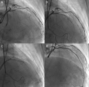
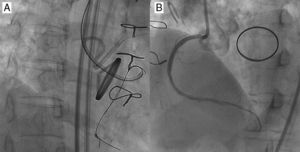
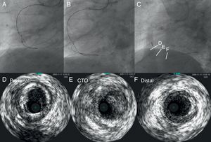
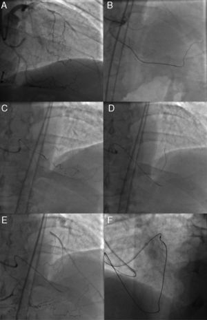
Unfavorable lesion features for PCI include long occlusions (in both length and duration), no stump, and presence of a large side branch with a takeoff adjacent to the occlusion. However, nearly half of all CTO are not accurately dated; careful history taking, previous records of electrocardiogram, echocardiograms and angiograms would be of help to estimate the duration of the occlusion. The high-quality X-ray imaging is among the important elements for successful PCI and avoiding complications, with bi-plane flat-panel systems preferable. Before the procedure, the importance of careful assessment of angiography cannot be overstated (Figure 1). Recently, high-resolution reconstruction images of coronary computed tomography (CT) scans are available and are of value in assessing CTO, especially in terms of their length and extent, and location and distribution of calcification, since presence of long occlusions and severe calcification are reported to be the major negative predictors of CTO-PCI.6

Figure 1. Need for detailed angiographic assessment. Initial angiogram missed the conus-to-septal collaterals, and therefore overestimated the characteristics of left anterior descending coronary chronic total occlusion (A). Actuarial length of occlusion was not long on more detailed dual injection (B); successful wire crossing and recanalization was achieved with a Miracle Bros® 3g and drug-eluting stent implantation, respectively (C-D).
To comprehend contemporary CTO-PCI, it is useful to compile the strategies into 2 major groups: single wire and dual wire approaches. Each has, in general, 3 escalating steps: first approaches with a soft, tapered, polymer jacket wire, second, a middle-weight spring-coil wire; and a high-gram tapered wire third. Dual approaches consist of using the parallel wire technique first, bilateral (retrograde) approach second, and the intravascular ultrasound (IVUS)-guided approach, last. When CTO-PCIs are attempted in this order after obtaining sufficient experience and skill, one could expect to have at least approximately a 90% chance of successful recanalization among selected patients with appropriate indications. Clinical background and situation will dictate whether a patient needs one-time or staged procedure or even 2nd or 3rd attempts in case of unsuccessful recanalization.
The definition of the CTO and indication of PCI are discussed extensively elsewhere7; therefore, this article specifically focuses upon current technical aspects of the procedure.
Device PreparationThe bi-femoral approach is characteristic for CTO-PCI (in case of no peripheral vascular disease), with side-hole guide catheters for each puncture site, one (≥7 F) for visualization of the distal collaterals and for possible retrograde access, and the other (≥7 F) for antegrade approach. To obtain further support, long femoral sheathes (≥30cm) are helpful, especially in the cases of tortuous arteries. Back-up support and side holes are the essential elements in guide catheter selection: an extra back-up or an Amplatz® type guide for the left coronary and an Amplatz® type for the right. A shorter guide catheter (<90cm) is also available on the market for the retrograde access. When IVUS-guided PCI is contemplated, it is better to use an 8 F guide catheter to accommodate 2 catheters (IVUS catheter and microcatheter).
The low profile, short tip IVUS (ie, VOLCANO®, San Diego, United States) is suitable for CTO-PCI guidance. Simultaneous double contrast injection is mandatory to visualize the distal vascular bed beyond the CTO, via the collateral-supplying side of the artery.
Guide wire selection and micro catheter based upon percutaneous coronary intervention strategyA number of dedicated CTO guide wires are available on the market (Table 1), but key elements to recognize are: a) tapered (0.009 in) or not; b) polymer jacket or not; c) stiffness, and d) trackability. For a focal tapered CTO without a side branch, for example, one can start with soft, tapered, polymer jacket wire for initial microchannel tracking. For an IVUS-guided re-entry from subintimal space to true lumen, one may require tapered, high-gram stiff wire. Since penetration force of a wire derives from tip load (stiffness), diameter, and lubricity, new operators can pick one or two work-force wires at the beginning to learn CTO-PCI. With a single wire strategy, one can start from soft, tapered, polymer jacket wire, middle-weight nontapered spring-tip and then, tapered, high-gram, stiff wires, depending upon the progression into the CTO segment. Although we cannot detail the pathologic basis of the CTO, a certain percentage of CTO contains the patent microchannels of 160 to 230μm, while remaining angiographically occlusive.8 Although the proximal CTO cap tends to be stiffer fibrocalcific plaque, compared with the distal CTO cap, recent application of soft polymer jacket wire in conjunction with a microcatheter has improved the chances of antegrade recanalization on a first attempt. As a result, “by chance” success could occur in up to half of the cases when selected types of CTO are attempted. Therefore, the first goal of CTO-PCI training would aim at least more than 70%-75% of procedural success (≤20% stenosis and Thrombolysis In Myocardial Infarction grade [TIMI] 3 flow) at a first attempt in an antegrade approach without major adverse complications.
Table 1. Guide Wires for Coronary Chronic Total Occlusions.
| Manufacturer | Wire | Diameter tip, inch | Tip load, g | Coating characteristics |
| Abbott vascular | Cross-It® 100, 200, 300, 400 | 0.0140-0.0110 | 2, 2, 3, 4 | Hydrophilic |
| Pilot 50®, 150, 200 | 0.0140 | 2, 3,6 | Polymer coated | |
| Whisper® LS, ME, ES | 0.0140 | 1, 1 | Polymer coated | |
| HT Progress® 40, 80, 120 | 0.0140 | 4.8, 9.7, 13.9 | Polymer coated | |
| HT Progress® 140T | 0.0105 | 12.5 | Polymer coated | |
| HT Progress® 200T | 0.0090 | 13.3 | Polymer coated | |
| Abbott/ Asahi | Miracle® 3, 4, 5, 6, 9, 12 | 0.0140 | 3, 4.5, 6, 9, 12 | Hydrophobic |
| Confianza® | 0.0140-0.0090 | 9 | Hydrophobic | |
| Confianza Pro® 9, 12 | 0.0140-0.0090 | 9, 12 | Hydrophilic, except the tip | |
| Confianza® 8-20 | 0.0140-0.0080 | 20 | Hydrophilic, except the tip | |
| Fielder FC® | 0.0140 | 1 | Polymer coated | |
| X-treme® | 0.0140-0.0120 | 0.8 | Polymer coated | |
| Terumo | Runthrough NS® | 0.0140 | 1-3 | Hydrophilic |
| Crosswire NT® | 0.0140 | 12 | Polymer coated |
Soft polymer wires include Pilot 50, Whisper® LS, HT Progress® 40 and Fielder XT® (tapered), middle weight spring wires Miracle® 3g, and 4.5g and Cross-It® 100 (tapered), high-gram wires Cross-It® 400 (tapered), Miracle® 12g, HT Progress® 200T (tapered), and Confianza Pro® (tapered) 9g and 12g.
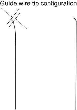
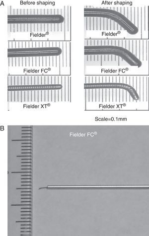
The wire tip should be shaped as short as possible in length, with an angle less than 45° initially. A second, milder curve would be preferable to improve maneuverability of the wire. One exception to the rule is illustrated at the right: a sharp (greater than 60°) angle with a 1 to 2mm bend, depending upon the lumen size, is required to navigate the wire from subintimal space back to true lumen either as a part of Parallel wire technique or IVUS guided wiring. The Confianza Pro® (9g or 12g, Asahi Intecc, Japan) or Pilot® 200 (Abbott Vascular, United States) is the best suited to this purpose.

Figure 2. Coronary chronic total occlusion guide wire configuration. The very short (<1mm), curved (<45°) tip of a wire is mandatory for initial coronary chronic total occlusion probing over a microcatheter. The sharper curve is needed in more specific situations.
Guide Wire HandlingThere are different methods of guide wire handling: drilling, penetration, and sliding strategies at proximal cap, inside CTO, and distal cap. Each method has advantages and disadvantages, but overall any method works well for a short, focal, straight segment of a noncalcified CTO. When it comes to a long, torturous, calcified occlusion, however, wiring should be tailored to lesion characteristics. Hard fibrocalcific plaques and tortuosity inside CTO remain major obstacles for PCI. Even a tapered, stiff wire cannot penetrate calcification, but can minimize crossing deviation. However, the wire tends to dig deeper into the subintimal layer at a tortuous or angled CTO segment. The author believes that combination of sliding and penetration strategy over a microcatheter would be preferable, paying special attention to the wire tip in relation to the target lumen in at least 2 different orthogonal views.
Microcatheter ( Table 2 )Low profile, trackable, over-the-wire microcatheters are an indispensable tool for CTO-PCI, as they allow precise guide wire control and ease of wire exchange. To make best use of STP® wires, it is crucially important to advance the microcatheter close to the tip to enhance wire control. When wire exchange is necessary, inject saline into the lumen to avoid introducing air. Also, when a microcatheter needs to be exchanged over a guide wire, balloon dilation (2.5mm inside of 7 F guide, for example) beyond the microcatheter can fix the wire and facilitate microcatheter exchanges (balloon trapping).
Table 2. Microcatheters Applicable for Coronary Chronic Total Occlusions.
| Manufacturer | Catheter | Shaft length (cm) and diameter (F) | Inner lumen size, inch |
| Cordis | Prowler® 14 | 150/1.9 | 0.017 |
| Prowler® 10 | 150/1.7 | 0.015 | |
| Transit® | 135/2.5 | 0.021 | |
| Abbott/Asahi | Tornus® 2.1 F | 135/2.1 | 0.016 |
| Tornus 88 Flex® 2.6 F | 135/2.6 | 0.024 | |
| Corsair® | 135/150/2.6 | 0.016 | |
| Terumo | Pro Great® | 130/150/2.4 | 0.019 |
| Finecross® | 130/150/1.8 | 0.018 | |
| Boston | Excelsior® | 175/2 | 0.019 |
| Excel® 14 | 150/1.9 | 0.017 |
| Manufacturer | OTW | Ball size (mm) and shaft length (cm)/caliber (F) | Tip profile, inch |
| Terumo | Ryujin plus® | 1.25×10/148/2.5 | 0.017 |
| Invatec | Falcon® | 1×10/140-160/2.2 | 0.016 |
| Abbott | Voyager® | 1.50×12/143/2.5 | 0.017 |
| Boston | Apex® | 1.50×9/135/2.3 | 0.017 |
| Medtronic | Sprinter® | 1.50×6/138/2.5 | 0.016 |
F, French; OTW, over the wire.
Among the available microcatheters, Transit® (Cordis, Miami, United States), Finecross®, Pro Great® (Terumo, Japan) have the advantage of large lumen and trackability for selective injection and tortuosity, whereas Corsair® (135cm, and 150cm, Asahi Intecc, Aichi, Japan) has more support, even beyond a calcified or tortuous segment.
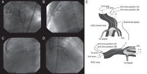
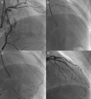
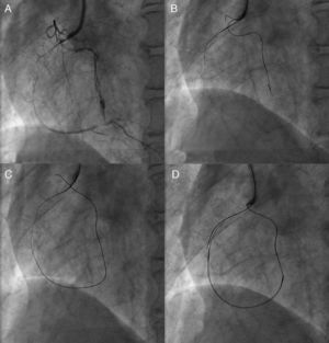
Parallel Wire TechniqueWhen a distal lumen fails to visualize as a guide wire crosses, this suggests the subintimal passage of the wire, expanding the area injured by the wire tip (the subintimal layer) and compromising the true lumen. Since the wire is at least inside the vasculature, the next step will be parallel wire technique with a stiffer wire before losing the sight of distal lumen. One case of the strategy is presented in Figure 3(A, B, C, D).

Figure 3. Parallel wire method. Percutaneous coronary intervention was attempted for a post-bypass left anterior descending coronary chronic total occlusion (A), in which the first wire of Miracle Bros® 3g went off-line from the target (B). Miracle Bros® 12g wire was used as a second wire to reach the distal true lumen (C). Parallel wire method allowed the second wire to access the coronary chronic total occlusion from a different entry, enhancing the chance of getting the distal true lumen (D). Figure 3E presents concepts of the method. 9 LAD, left anterior descending artery; DX1, first diagonal artery; RAO, right anterior oblique.
The first step is to leave the first wire in place, to help with visualization and minimize contrast injection. The second wire can then be advanced over a microcatheter to facilitate steering into the true lumen. Key points are: a) the second wire should be a stiffer and more torquable one, such as Confianza Pro® 9g or Pilot® 200; b) the wire should start from a different CTO entry point, using at least 2 different orthogonal views; c) penetration wiring will minimize expansion of the injured area, and d) time for wiring will be limited due to potential expansion of the subintimal space (and eventual loss of distal vessel visualization). Schematic illustration is reproduced in Figure 3E.9
IVUS Navigated WiringIVUS is one of the imaging modalities to depict a cross sectional view of the coronary tree, which can focus upon plaque distribution, calcification, reference vessel size, and side branch anatomy. Hence, IVUS can be applicable in CTO-PCI in the setting of: a) side branch method to navigate CTO wire into the true lumen from the proximal cap, and b) subintimal re-entry from the proximal true lumen. Currently, IVUS guided subintimal re-entry would be the last resort for getting a subintimal wire into the distal true lumen, since the method can be applicable, even after losing site of the distal vascular bed on angiography. After 1.5mm or 2mm balloon dilation in the presumed subintimal space, IVUS is advanced into the space and is monitored to orient the second wire to true lumen. Key points are: a) ability to translate cross-sectional images of IVUS into 3 dimensions is needed; b) the second wire should be a stiff, tapered wire over a microcatheter; therefore, an 8 F guide is mandatory; c) re-entry point should be closer to the proximal cap, and d) contrast injection should be withheld, especially after small balloon dilation. Thus an operator must understand the anatomy of coronary arteries in terms of IVUS interpretation.
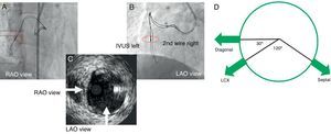
Conceptually, Figure 4 describes IVUS images of the left coronary system and main branches. Cross-sectional images of IVUS are basically the views looking down from the ostium and from the patient's head. If 12 o’clock were assumed at anteroposterior cranial position, the left anterior descending artery commonly shows the side branch anatomy with the diagonal at 9 o’clock, the septal at 4 o’clock, and the left circumflex artery at 8 o’clock. Therefore, clear orientation in relation to the side branches can permit a second guide wire to direct into the true lumen. The right coronary artery and the left circumflex artery have a variation of side branch anatomy; therefore, a 2-wire method is the best to define a specific angiographic view in relation to a tomographic image of IVUS (see details in Figure 4).

Figure 4. Two-wire method for right coronary or left circumflex arteries and model of left coronary system (a view from left main trunk to left anterior descending artery) to orient intravascular image into the corresponding angiographic projections.A: shows intravascular ultrasound probe and second guide wire in overlapping projection in right anterior oblique. B: shows most widely separated projection being intravascular ultrasound on the left to the second wire in left anterior oblique view. Therefore, the corresponding intravascular ultrasound image in Figure 4C reveals a true lumen at the 3 o’clock, and projectile angiographic views of left anterior oblique at 6 o’clock and of right anterior oblique at 9 o’clock (right anterior oblique is positioned at 90° clockwise from left anterior oblique view). The second wire should be directed to the inner side (right to the intravascular ultrasound probe) on left anterior oblique view to get the true lumen. Figure 4D provides anatomical relationships of major left coronary artery branches in cross-section of intravascular ultrasound. IVUS, intravascular ultrasound; LAO, left anterior oblique; LCX, left circumflex; RAO, right anterior oblique. Courtesy of Dr. Asakura and Dr. Kato in Toyohashi Heart Center.
Importance of Wire Crossing From True to True LumenOnce the wire reaches a distal true lumen through subintimal wire crossing in some segment without compromising many side branches, subintimal stenting might be practical in term of less radiation time and amount of contrast, compared with a further effort to redirect the wire to a true lumen from the entry point. The larger the distal vascular bed integrity, the better the chance of achieving restoration of TIMI 3 flow. Long term patency seems to be excellent with drug eluting stents. However, when a guide wire is steered into the distal segment of a true lumen supplying a limited area of myocardium, stenting may result in suboptimal flow, especially in case of a side branch being sheared off. The slow flow at the end will be associated with a high propensity of restenosis or even re-occlusion. Therefore, CTO-PCI should be planned to minimize subintimal wiring and maximize a long-term benefit of stenting (although in some cases subintimal wiring and stenting is practically unavoidable in a case of severe fibrocalcific occlusion over a negatively remodeled segment). IVUS would be of great help to determine the guide wire position when available, but sound clinical judgments have no substitute in the context of successful recanalization.
Retrograde Approaches in Coronary Chronic Total Occlusions- Percutaneous Coronary InterventionAlthough retrograde techniques were, in the past, applied to a number of CTO, limited success was achieved. Examples of these early techniques include kissing wire (Figure 5), knuckle wire, and direct retrograde crossing (Figure 6, Figure 7). The major shortcomings of these techniques have, however, been applicable only to certain lesion subsets and, furthermore, limited successful recanalization. The rationale and technique used here are quite different from those of conventional PCI; the operator should have a sound grasp of antegrade approach before embarking on a retrograde CTO procedure.

Figure 5. Kissing wire technique. An antegrade wire crossed exactly in the same lumen of the coronary chronic total occlusion with a retrograde wire in a right anterior oblique view (A) and could reach distal true lumen (B).

Figure 6. Knuckle wire technique. In case of left anterior descending artery coronary chronic total occlusion (A), retrograde wire is advanced with a looped wire tip pushed deeper into the occlusion (B) to facilitate antegrade wire advancement for creating subintimal dissection (C), resulting in successful recanalization (D). The technique is, however, usually hampered by an uncontrollable degree of dissection and a possibility of shearing off the side branches.

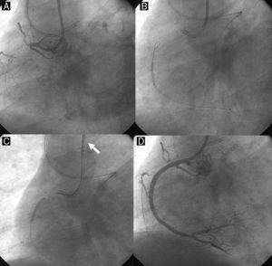
Figure 7. Direct retrograde wire crossing. A retrograde wire, supported by an over-the-wire balloon (A and B), could cross a coronary chronic total occlusion into the proximal vascular lumen, (and eventually) into the antegrade guide catheter (retrograde wire tip indicated by white arrow) (C). Over this wire, a retrograde balloon could dilate the coronary chronic total occlusion and complete the procedure with antegrade wiring and stent deployment (D).
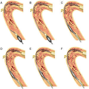
Controlled Antegrade and Retrograde Subintimal TrackingIn 2005, a more comprehensive retrograde approach was developed by Dr. Kato. The CART® (controlled antegrade and retrograde subintimal tracking) technique consists of antegrade wiring through the CTO where retrograde balloon dilation creates a local subintimal dissection for facilitating wire crossing to the distal true lumen.10 The figure explains how retrograde balloon dilation contributes to mobilize the 2 separate wires, merging into the same lumen (Figure 8).

Figure 8. Concept of CART®. 10 Antegrade wire is advanced into the coronary chronic total occlusion, then into the subintimal space. The retrograde wire is placed at the distal end of the coronary chronic total occlusion, then introduced into the coronary chronic total occlusion, and finally into the subintimal space (A). After advancing a small balloon (1.5–2mm) over the retrograde wire into the subintima (B), the balloon should be inflated inside the coronary chronic total occlusion (C). To keep this subintimal space open, the deflated balloon should be left in place (D). The two subintimal dissections provide a “re-entry space” for the antegrade wiring (E). Thereafter, the antegrade wire is advanced further along the deflated retrograde balloon into the distal true lumen (F). This technique allows limited subintimal tracking (dissection) only in the coronary chronic total occlusion segment and avoids the difficulty of re-entering the distal true lumen. CART®, controlled antegrade and retrograde subintimal tracking.
It is crucially important to use the closest sized balloon inside of CTO to create sufficient wire re-entry space (Figure 9). Access to the distal CTO was explored mainly through septal collateral channels by a polymer jacket wire over a microcatheter or over-the-wire balloon; therefore, septal channel dilation by 1.25mm balloon at low pressure was required to advance a bigger size of over-the-wire balloon later. The major limitations are limited access of the collateral channels to the target CTO, empiric estimation of the retrograde balloon size, and overall unpredictable procedure time.

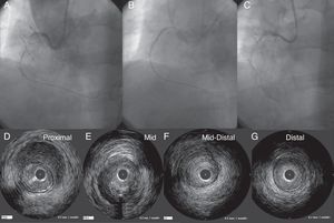
Figure 9. A case of CART®. Smaller size of a retrograde balloon was not large enough to create a “re-entry space” for an antegrade wire on CART® (A). On the right hand panel, a larger (2.5mm) balloon had successfully provided the “space” for an antegrade wire re-entry (B). White bars indicate the level of corresponding intravascular ultrasound images (C). In intravascular ultrasound, proximal segment of coronary total occlusion revealed the probe inside of the true lumen (D), whereas inside the coronary chronic total occlusion, the probe was outside the high echogenic true lumen (E). In the distal segment, the probe returned in the true lumen (F). This represents the typical intravascular ultrasound findings after the successful “CART®”. CART®, controlled antegrade and retrograde subintimal tracking; CTO, coronary chronic total occlusion.
In one registry data, a total of 157 consecutive patients (previous failed PCI, 75.2%) underwent retrograde PCI for CTO.11 Successful retrograde recanalization was achieved in 65.6%, overall technical success in 85%. The collateral crossing was achieved via septal in 67.5%, epicardial in 24.8%, and bypass grafts in 7.6%. Fielder FC® is the most often used in collateral crossing. Retrograde approach was completed with an implementation of CART® in 40.8%, direct wire crossing in 24.8%. CTO crossing was achieved mainly by softer wires in retrograde approach. Major and minor collateral injury and delayed cardiac tamponade occurred in 0.6%, 10% and 0.6%, respectively. No episode of mortality occurred in this cohort. Non Q wave myocardial infarction (QWMI) was noted in 3.2%, QWMI and emergent PCI in 0.6%.
Reverse CART® TechniqueWith the advent of soft, polymer jacket wires and micro catheters, more complex collaterals have been successfully crossed in a retrograde fashion. By 2008, the concept of a channel dilator materialized as the Corsair® microcatheter (Asahi Intec, Aichi, Japan), which enables the wire to access the distal CTO through any collateral, including septal, atrial, and epicardial, channels.12 When the retrograde wire crosses CTO close to the proximal cap, antegrade IVUS can confirm the retrograde wire position and the balloon size based on the reference vessel size. Then, an appropriately sized balloon can fully dilate the CTO to create an optimal re-entry space for the retrograde wire. Once the wire enters the guide catheter, Corsair® can also be advanced over the trapping wire to exchange the wires for 300cm wire externalization. Over this long wire, additional “antegrade” balloon dilation and stent delivery can be achieved. This is a beginning of the current predictable and reliable retrograde approach called IVUS-guided reverse CART®, which was also developed by Dr. Kato. In their report, retrograde recanalization achieved a 100% success rate in 31 CTO; an application of Corsair®, 87%; and predominant re-entry implementation of reverse CART® with IVUS guidance, 93.5%.13 However, CART® was still needed in 6.5% of the cases. Therefore, the methods are complementary to achieve high CTO recanalization rates.13 Figure 10 shows a case example of this technique.

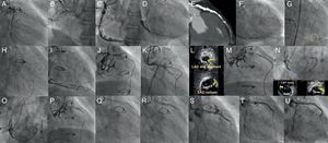
Figure 10. A case of reverse CART®. In post coronary artery bypass graft angina, the vein graft to left anterior descending artery was occluded, as were a native left anterior descending and right coronary artery (A and B), and the posterior descending artery was visualized through the degenerated vein graft (C). The distal left anterior descending was supplied by the right to left collaterals mainly through the septal branches (D). Coronary computed tomography scan demonstrated left main trunk-left anterior descending coronary chronic total occlusions with thick, heavy calcification with no hint of luminal space (E). Three well developed collaterals, connected to the distal left anterior descending, were noted on rotational angiography from right anterior oblique caudal to anteroposterior caudal (F). Super-selective injection delineated the collateral channels clearly, especially severe bending in the lower septal segment (dashed circle, G). The second deepest septal was a possible channel for the retrograde wiring (H). Since the first wire of Fielder FC® failed to cross the lower tortuosity, Fielder XT® was tried, resulting in successful crossing (I). Corsair® was then advanced over the Fielder XT® into the distal left anterior descending, and the retrograde wire was exchanged to the Fielder FC® (J). Since the wire failed to penetrate into the proximal vascular lumen, as is often the case (K), intravascular ultrasound was advanced to find the wire right next to the calcified plaque (cross-section of the wire is indicated by yellow arrows), and measure the size of the reference vessel (3-3.5mm) for wire re-entry (L). The 3mm balloon was fully dilated at 10-12 atm, while the retrograde wire was manipulated toward the balloon (M). (Of note, this is a “CART®”, in which a wire re-entry was mediated by antegrade balloon dilation inside of vascular space). With the retrograde wire of Miracle Bros® 3g, the wire entered the antegrade guide catheter. Intravascular ultrasound disclosed the wire position inside the true lumen (wire indicated by yellow arrows) (N). Corsair could cross further into the guide catheter, over which the wire could be exchanged to a longer guide wire (RG3®330cm, Asahi Intecc, Aichi, Japan) to externalize from the other side of Y-connector (O). Then 1.5mm and 2.5mm balloon was dilated over the externalized wire. A double lumen catheter was used to place the second wire to the distal left anterior descending artery (P). The retrograde system could be pulled back, first advancing Corsair into the mid left anterior descending to visualize collaterals over the wire to check channel injury. Antegrade 2mm balloon was dilated throughout the course (Q), and 2.5×28mm and 3×33mm drug-eluting stents were deployed (R). Although post-stent balloon dilation resulted in coronary perforation (S), which was promptly treated by “Graft Master®” stents (Abbott Vascular, United States)”, the procedure was successfully terminated (T). Eight-month follow-up angiography revealed no restenosis (U). In this case, a so-called “blooming effect” on computed tomography scan led to overestimation of the unlikelihood of successful recanalization. CART®, controlled antegrade and retrograde subintimal tracking; LAD, left anterior descending artery; LTM, left main trunk.
The stiffer wire is in general least recommended for use as a retrograde wire, although application would not be unreasonable under certain specific conditions. Those include presence of hard fibrocalcific plaque, a straight segment, and close proximity with antegrade equipment. Indiscriminate application of retrograde stiff wires could aggravate the procedure. For example, in the setting of reverse CART®, the stiffer retrograde wire might go into the deeper subintimal space beyond the re-entry space, especially in the absence of IVUS guidance.
A word of caution regarding this technique: once the antegrade balloon is dilated for the retrograde wire re-entry, contrast injection should not be used until the last stent deployment. Otherwise, pressurized contrast injects into the dilated segment, causing a spiral dissection or hematoma (hydropressure-induced dissection) (Figure 11).

Figure 11. A pitfall of reverse CART®. A-C: depict a case in which a small amount of contrast created a large hematoma after retrograde wire re-entry, and required additional stents to cover. D-G: proximal to distal.
Potential Candidates for the Retrograde ApproachThe retrograde approach is a new and still evolving technique. Compared with the conventional antegrade approach, a higher rate of success can be expected from the combination of antegrade and retrograde approaches. Collateral channel crossing with a guide wire is reportedly achieved in 73% to 87% of cases in experienced hands.10, 11 Since conventional angiographic features contraindicating PCI, such as a blunt occlusion with a large side branch, bridging collaterals, calcification, and long CTO are no longer considered negative predictors of retrograde procedures,11 considerable subsets of previous antegrade failures are good candidates for this new approach.
Possible acceptable candidates would include: a) previous failed patients with a clear indication who are highly motivated for PCI; b) refractory angina with native CTO in post-surgery coronary artery bypass graft patients; c) single-vessel disease, either nonostial left anterior descending artery or right coronary artery CTO with preserved left ventricular and renal function, and d) patients with multivessel disease and comorbidities who decline coronary artery bypass graft surgery.
The next step begins with scrutiny of the previous coronary artery disease or PCI records and any imaging modalities, focusing on the potential collateral route, degree and location of the calcification, and the potential sources of complications.
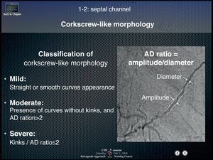
Collateral crossing with a guide wireThree elements should be kept in mind for successful collateral crossing: a) channel selection; b) wire tip curve, and c) wire handling. The best collateral channel for retrograde wire crossing is clearly visualized, less tortuous collaterals by super-selective injection, exemplified by Dr. Werner's collateral connection (CC) grade 1 or 2 (CCs were graded as follows: CC0, no continuous connection, CC1, continuous thread-like connection; and CC2, continuous, small side branch-like connection).3 On the other hand, major obstacles of wire crossing are acute angulations, sharp bend, branching, cork-screw morphology, calcification, and nonvisibility of the CC connection with the recipient vessel.11 A rule of thumb to avoid failure would be not to choose severe corkscrew-like collaterals, characterized by an amplitude to diameter ratio less than 2 (Figure 12) (courtesy of Dr. Kato, 2008 CCT presentation).

Figure 12. Differential formula for corkscrew-like collateral channels. Amplitude to diameter ratio of the corkscrew less than 2 defines severe tortuosity of the collateral channel and usually precludes successful wire crossing. AD, amplitude to diameter.
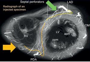
In case of right coronary artery CTO, right anterior oblique cranial position is the best view on angiography for screening the septal collaterals from left anterior descending artery, whereas right anterior oblique caudal view provides the true length of collateral (Figure 13).14, 15

Figure 13. Anatomical relationships of septal channels on angiographic views. right anterior oblique cranial view (green arrow) is the best en face view of the origin of left anterior descending artery septal branches, while right anterior oblique caudal (yellow arrow) is best for the lower septal branches. Usually, branching from the left anterior descending artery allows more feasible wiring, compared with lower branches of posterior descending artery with more tortuous, branching, and corkscrew aspects. apm, anterior papillary muscle; LAD, left anterior descending; LV, left ventricle; OM, obtuse marginal; PDA, posterior descending artery; ppm, posterior papillary muscle; RAO, right anterior oblique; RV, right ventricle.
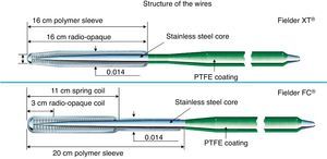
Two kinds of polymer jacket wires are suitable for collateral channel crossing. Nontapered 0.014″ (0.36mm) wires such as Fielder FC® (Asahi Intecc, Japan), Whisper® wire (Abbott Vascular, United States), and 0.009″ (0.23mm) tapered wire such as Fielder XT® (Asahi Intecc, Japan) (Figure 14). Both have floppy strength at the tips with hydrophilic polymer coating. When the channel is considered to be a substantial size, CC 1 or 2 (>0.4mm, lower limit of visibility on 512×512 DICOM® Format), Fielder FC® would be the first try, whereas if some part is estimated less than 0.4mm and has minor tortuosity on CC 0 or 1, Fielder XT® would be recommended.

Figure 14. Structure of Fielder XT® and FC® wire. PTFE, Polytetrafluoroethylene.
Regarding the wire tip curve, an extremely small tip curve (<1.0mm) is recommended (Figure 15A) after the micro catheter is navigated to the proximal segment of the collateral channel by a normal floppy wire. Since the tip of those wires is soft, gentle tapping of the wire tip on the insertion needle would be the best method to create a curve (Figure 15B).

Figure 15. Wire tip curve necessary for channel crossing. Extremely small curve (<1mm) on soft polymer jacket wire is recommended (A). Initial curve would better be shaped on top of an insertion needle (B).
Regarding wire handling, it should be gentle with slow rotation, and should advance and halt once a series of ventricular premature contraction has developed or migration to the side branch is noticed. Forceful advancement and rotation could result in channel rupture, vessel perforation, and eventual septal hematoma, which would be fatal after several hours without proper management (ie, embolization of the channel). Therefore, utmost care should be paid to manipulate the wire in the collateral channels.
Whenever the wire position is in doubt, advance the micro catheter and pull back the wire to inject contrast (as little as 2ml) to determine the direction to follow. When an injection reveals washout of the contrast, the channel is connected to either the right ventricular or the left ventricular cavity. When the contrast stays in the channel, it infers local disruption (focal perforation). Those are the examples in which no further treatment is required and other channels would better be explored. Finally, when reverse CART® is contemplated, a long floppy wire (RG3® wire, or Fielder FC® 300cm, Asahi Intecc, Japan) should be available at hand for retrograde wire externalization.
Fielder XT-R® WireRecently, a softer tip, tapered (0.009″) polymer jacket wire has been developed in Japan, which could be safely used for septal, atrial, and epicardial collaterals. The wire tip is characterized by kink-resistant “rope coil” structure and the same design is adopted in nontapered, floppy Sion Blue® wires. A representative case is Figure 16.

Figure 16. A case of Fielder XT-R®. The case was a right coronary artery coronary chronic total occlusion with an 8 F short Amplatz® 1 side holes guide for antegrade approach (A). Since the Miracle Bros® 3g and Confianza Pro® 9g could not reach distal vascular lumen, Fielder XT–R® was introduced into the ipsilateral conus branch (B), which successfully crossed the collateral over the Corsair® (C). Antegrade Fielder XT® wire was also advanced to the middle segment as part of the bilateral approach (D).
Sion Blue Wire®This is also a new floppy wire from Asahi Intecc, Japan, which specifies a 0.014″ size and a more tortuosity-resistant spring tip. A representative case is Figure 17.

Figure 17. A case of Sion blue® wire. The case is a coronary chronic total occlusion of proximal left anterior descending artery, with a 7 F short Amplatz 1 side holes guide for the right and 7 F extra-backup 3.5 SH® guide for the left (A). Since wiring through the septal branch had failed, wire crossing was explored through a conus-to-septal connection (B). Sionblue wire could reach to the septal over the Corsair® (C), where the 60° tip curve was successful in crossing the sharp turn to the left anterior descending artery (D). After confirming the wire position (E), Corsair® was advanced into the proximal left anterior descending artery (F).
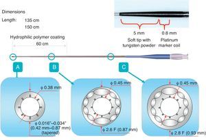
Microcatheter and Corsair®Corsair® (Asahi Intecc, Japan) is a microcatheter with a braiding of 10 wires interwoven to form a metallic tube with a length of 135cm and 150cm (Figure 18), which is covered in a polymer. A 0.21″ shaft has a Tornus® (Asahi Intecc, Japan)-like structure with a tip covered by a tapered soft nose cone (0.016″) to enhance crossability in the microchannel and the maneuverability of a retrograde guide wire. Tip to body, the Corsair is hydrophilic-coated to enhance lubricity with the rotational torque needed to advance and retrieve through the collateral channels and CTO. This catheter can be applicable for many collateral channels without any balloon dilation. There are a few principles to be kept in mind in controlling the device:
1. Gentle rotation is recommended to advance or pull (by either clockwise or counterclockwise rotation).
2. Once strong resistance is met inside of a channel, maintain gentle rotation. If it cannot cross, then pull back the device and exchange for a low-profile microcatheter or over-the-wire balloon system. Both should have the longer shaft (>145cm) to steer into the CTO over a collateral channel.
3. When removing the retrograde devices, make sure that pulling them does not bring the guide catheter deeper inside the coronary ostium. The tip of the guide can cause injury, dissection, and eventual occlusion. A representative case is Figure 19.

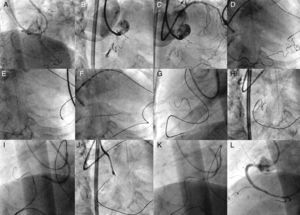
Figure 19. A case of Corsair®. The case is a coronary chronic total occlusion of the proximal right coronary artery with a sharp angle at the ostium in right anterior oblique cranial (A, B). Guide catheters consisted of 7 F extra-backup 3.5 side holes for the left, and 7 F short Amplatz® 1 side holes for the right. A part of distal right coronary artery was supplied by a very tortuous ventricular branch, from the apical segment, left anterior descending artery (C). Super selective tip injection was conducted to delineate the epicardial-ventricular collateral from the distal left anterior descending artery (D). Sion Blue® wire crossed first the proximal one-third of the collateral with Corsair® support, and then crossed further down over severely curved segments with a newly created tip curve (>45°) (E). Since Corsair® did have difficulty in crossing, the wire was further advanced intentionally into the posterolateral branch (F). Gentle rotation over the wire being pulled enabled Corsair® to cross through the entire collateral (G), and then the wire tip was redirected to the coronary chronic total occlusion (H). The wire was exchanged to Confianza Pro® 9g to cross the occlusion (I, J) and wire re-entered the antegrade guide by intravascular ultrasound-guided reverse controlled antegrade and retrograde subintimal tracking (K). Final angiography revealed excellent results (L).


Figure 18. Configuration of Asahi Corsair® microcatheter.
In one study, application of Corsair® was associated with a higher rate of retrograde recanalization in 98.8% (n=93), compared with the non-Corsair® group of 92.5% (n=93) after successful retrograde wire crossing through a collateral channel (P=.030).12 Corsair® was also associated with higher chance of collateral channel (96.8%) and CTO crossing (84%) without increasing either major or minor collateral injuries. Implementation of a retrograde approach was predominantly reverse CART® of 60.9%, followed by retrograde crossing of 20.6% in Corsair® group, whereas in the non-Corsair® group there was a CART® of 64% and retrograde wire crossing of 24.4% (P<.0001). Finally, total fluoroscopic and whole procedure time tended to be shorter in Corsair® group (60.1 [26.3] vs 67.8 [29.1] min, P=.087 and 135.6 [57.4] vs 155.5 [65] min, P=.078, respectively).
Complications Associated With the ProcedureSpecific complications associated with a retrograde approach are collateral channel rupture, thrombus formation, and global ischemia. As already mentioned, most channel ruptures do not require further treatment,11 except in cases of septal hematoma or cardiac tamponade, in which definitive hemostasis is required by embolic occlusion via a microcatheter. Microcoils are required to embolize the ruptured segment of channel in the case of tamponade-prone bleeding. Therefore, before pulling out the retrograde wire, the donor side of the arterial tree should be visualized with the externalized wire in place. Then, microcatheters from both ends of the externalized wire could allow access to a bleeding point, should collateral rupture occur.
Thrombus formation is also prevented by saline flush of the guiding catheter and by maintenance of activated clotting time >300s, checked every 30 to 60min. Global ischemia can be minimized by careful manipulation of the retrograde system in relation to the retrograde guide catheter engagement. Therefore, when there is a substantial coronary stenosis en route to the collaterals of donor side, advance treatment by stent allows for safer and stable retrograde instrumentation. Finally, catheter-induced dissection, which can most often occur when the retrograde devices are withdrawn, could be prevented by constant pulling of the guide catheter to disengage from the ostium, while gentle rotation (in either direction) of the Corsair® is executed to withdraw it.
Future PerspectiveThe retrograde approach has further been refined and simplified with more application of the softer polymer-coated wires, IVUS, and Corsair®. More cases will be managed by reverse CART®, while conventional CART® is still needed in cases of ostial occlusions, some heavily calcified occlusions, and when the microcatheter is unable to enter the occlusions, among others. Table 3 displays the major characteristics of CART® and reverse CART®.
Table 3. Comparison of CART® and Reverse CART®. The Table Highlights the Differences in the Wire “Re-Entry” Methods.
| CART® | Reverse CART® | |
| Main wiring | Antegrade | Retrograde |
| Wiring aid | Fluoro. alone | Fluoro. and IVUS |
| Re-entry mode | Sub-intimal tracking | Sub-intimal tracking |
| CTO re-entry techniques | Retrograde balloon | Antegrade balloon after IVUS |
| Reproducibility | Needs experience | High in experienced hands |
| Risks | Same as antegrade CTO + channel damage | Channel damage |
| Procedure time | Unpredictable | Predictable |
CART®, controlled antegrade and retrograde subintimal tracking; CTO, coronary chronic total occlusion; fluoro., fluoroscopic image; IVUS, intravascular ultrasound.
Although there are no conclusive prospective, controlled, randomized trials yet to support or dispute whether CTO-PCI is beneficial, we should perform CTO-PCI with caution, since new device application and evolving technique might associate complex CTO procedures with unimaginable complications. There is a hope that new imaging modalities, such as coronary CT scan, may facilitate planning and performing CTO procedures in a more reliable and predictable manner. Current unresolved issues include long-term effects of X-ray irradiation on the patients, contrast effect on renal function, and need for dedicated training to obtain the necessary technical skills.
Supplemental informationInterested readers can further refer to the books dedicated to deepening our understanding of each topic discussed above.15
Conflicts of interestNone declared.
Corresponding author: Cardiology Division, Sekishinkai Sayama Hospital, 1-33, Unoki, Sayama City, Saitama 353-1323, Japan. masahisa-yamane@sayamahp.org