Mitral regurgitation is the most prevalent valvular heart disease in the United States and the second most prevalent in Europe. Patients with severe mitral regurgitation have a poor prognosis with medical therapy once they become symptomatic or develop signs of significant cardiac dysfunction. However, as many as half of these patients are inoperable because of advanced age, ventricular dysfunction, or other comorbidities. Studies have shown that surgery increases survival in patients with organic mitral regurgitation due to valve prolapse but has no clinical benefit in those with functional mitral regurgitation. In this scenario, percutaneous repair for mitral regurgitation in native valves provides alternative management of valvular heart disease in patients at high surgical risk. Percutaneous repair for mitral regurgitation is a growing field that relies heavily on imaging techniques to diagnose functional anatomy and guide repair procedures.
Keywords
Mitral regurgitation (MR) is the most prevalent valvular heart disease in the United States and the second most prevalent in Europe.1–3 Competent mitral valve (MV) function requires the synchronization of several structures to direct blood flow from the atrium to the ventricle in diastole and vice versa in systole. Primary MR is organic failure of the structures that form part of the mitral apparatus. The most frequent etiology of primary MR used to be rheumatic disease but is now degenerative valve disease.2,3 Secondary or functional MR is due to subvalvular apparatus distortion or dysfunction due to ventricular enlargement or remodeling, or ischemia.4
Patients with severe MR have a poor prognosis with medical therapy once they become symptomatic or develop signs of significant cardiac dysfunction (ventricular dysfunction, pulmonary hypertension, or recurrent atrial fibrillation).3,5–8 However, as many as half of these patients are inoperable because of advanced age, ventricular dysfunction, or other comorbidities.9 Studies have shown that surgery increases survival in patients with organic MR due to valve prolapse5,10 but has no clinical benefit in those with functional MR.11
In this scenario, percutaneous repair for MR in native valves provides alternative management of valvular heart disease in patients at high surgical risk.12 Percutaneous repair for MR is a growing field that relies heavily on imaging techniques to diagnose functional anatomy and guide repair procedures.
Echocardiography is the primary imaging technique used to evaluate cardiac valves due to its high spatial-temporal resolution, availability, portability, and cost-effectiveness. Transesophageal echocardiography (TEE) is the gold standard in mitral leaflet guidance procedures due to many years of experience with mitral valve ultrasound studies. However, TEE has a restricted field of view, and as a result, multidetector cardiac computed tomography (cardiac CT) has been developed, which permits a comprehensive assessment of the mitral valve apparatus.
The different percutaneous repair interventions for MR are based on surgical techniques, including leaflet plication (MitraClip), annuloplasty (Carillon, Mitralign, Accucinch, Cardioband), neo chordae (NeoChord, V-Chordal), and percutaneous bioprosthesis implantation (CardiAQ, Fortis, TIARA, Tendyne).13–15 In Europe, MitraClip, Carillon, and NeoChord have marketing authorizations. MitraClip is currently the most widely-used device, with more than 25 000 implantations worldwide and more than 270 cases in Spain.16
MITRAL VALVE ANATOMYKnowledge of normal MV anatomy is essential to understand MV functioning and the mechanisms that lead to valve regurgitation, and to identify findings observed in different imaging techniques.
The mitral valve apparatus is composed of a fibrous annulus at the atrioventricular junction where the valve leaflets are attached, and a subvalvular apparatus composed of chordae tendineae (CT) and papillary muscles (PM) that insert into the myocardium in the left ventricle (LV).
Mitral AnnulusThe MV annulus is described as a saddle-shaped fibrous structure. Its peaks are furthest from the ventricular apex and are located anteriorly (at the “riding horn”) and posteriorly, and its valleys are located medially and laterally, at the commissures.17–19 The mitral valve is attached to the annulus. The annulus provides atrioventricular electrical isolation.
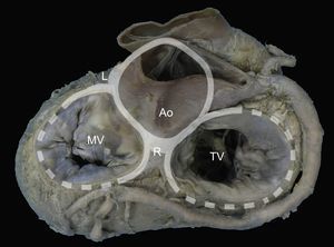
The presence of a complete ring of connective tissue encircling the atrioventricular junction is very rare.20 A thickened, fibrous band acts as a hinge at the aortomitral junction, between the right and left fibrous trigones. This discontinuous membranous band extends along the atrioventricular junction and is the site where the posterior leaflet and left atrium are attached21 (Figure 1).
 through the right and left fibrous trigones and the aortomitral junction, between the fibrous trigones. Ao, aorta; L, left fibrous trigone; MV, mitral valve; R, right fibrous trigone; TV, tricuspid valve.")
Mitral annulus. Macroscopic view of the base of the heart showing the mitral annulus in relation with the fibrous skeleton (denoted in grey by the aortic and tricuspid annuli) through the right and left fibrous trigones and the aortomitral junction, between the fibrous trigones. Ao, aorta; L, left fibrous trigone; MV, mitral valve; R, right fibrous trigone; TV, tricuspid valve.
The mitral valve consists of a continuous veil-like structure inserted around the mitral annulus. The free edge of this veil has several indentations or clefts.22 Two of these indentations are positioned in such a way that the structure is divided into 2: the anterior or aortic leaflet, and the posterior or mural leaflet. These 2 main indentations are known as the anterolateral and posteromedial commissures and are characterized by having a clear, translucent central zone, and no distal rough zone. The PMs point toward the commissures.22
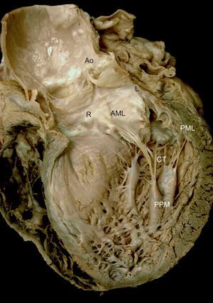
The anterior or aortic leaflet is large, triangular, with few or no indentations. Its atrial surface has a rough, crescentic ridge occupying 1cm of the distal free edge of the leaflet. The ridge defines the leaflet line of closure and its thickness is due to abundant chordal insertions in the ventricular surface in this area. A clear, translucent zone is distinguished beyond the rough zone, followed by a zone near the base for chordae attachment22,23 (Figure 2).

Mitral valve apparatus. Macroscopic view of a long axis slice of the heart through the anterior wall and aortic valve, without the anterior papillary muscle and its chordae tendineae. Note the relation between the anatomic structures and mitral apparatus anchoring to the ventricle via the papillary muscles. Note also how the chordae tendineae insert into the rough zone of the anterior leaflet ventricular surface and extend toward the aorta through the aortomitral junction, with the right and left fibrous trigones on either side. AML, anterior mitral leaflet; Ao, aorta; CT, chordae tendineae; L, left fibrous trigone; PML, posterior mitral leaflet; PPM, posterior papillary muscle; R, right fibrous trigone.
The posterior or mural leaflet is shorter than the anterior leaflet and has a wider attachment to the atrioventricular annulus. The indentations along the free edge give it a scalloped appearance, which varies greatly among individuals. The Carpentier nomenclature24 is used to describe the different scallops or segments: P1 is the most lateral scallop, adjacent to the anterior commissure; P2 is the middle or central scallop, and P3 is the most medial scallop, adjacent to the posterior commissure. The corresponding part of the anterior leaflet located opposite each scallop is named similarly: A1, A2, and A3, respectively. The posterior leaflet has 3 zones: a rough zone, where the line of the leaflet closure is located, a clear or membranous zone, and a basal zone.
Chordae TendineaeThe CT are thin, fibroelastic strings25 that originate from the PMs or directly from the ventricular wall and insert into the ventricular surface of the MV (true CT), or connect between PMs or with the ventricular cavity (false CT). On average, 25 CT insert into the MV and most branch out.26 Two main groups of chords are distinguished by their insertion site and branch location:
- •
Commissural chordae: These 2 CTs arise from the PM tips and branch out radially like the struts of a fan. They insert into the free edge of the commissures. Commissural chordae are 0.7-1 mm thick and 12-14 mm long.
- •
Leaflet chordae:
- –
About 9 CTs insert exclusively into the distal, rough zone of the anterior leaflet. Typically, each chord splits into 3 soon after its origin from the PM. One inserts into the free edge of the leaflet, 1 beyond the free edge in the same rough zone, and an intermediate one inserts between the 2. On average, these chordae are 0.84 mm thick and 17.5 mm long. Two chordae are particularly thick (1.24 mm) and they insert into the ventricular surface of the line of coaptation between the 4 and 5 o’clock positions (on the posteromedial side) and between the 7 and 8 o’clock positions (on the anterolateral side). These chordae are termed struts and were present in more than 90% of the hearts examined in the study by Lam et al.26
- –
Three types of CT insert into the posterior leaflet. The most characteristic ones are basal chordae that originate directly from the ventricular wall or from small trabeculae carneae. They are sometimes missing altogether and may vary considerably in number, but, on average, 2 basal chordae can be found. Similarly to the anterior leaflet CTs, 10 chordae insert into the rough zone of the posterior leaflet, although they are generally thinner and shorter (0.65 mm and 14 mm, respectively), and 2 others insert into the indentations, adopting a similar radial branching disposition to the commissural chordae.
- –
Papillary muscles are specialized cones of LV myocardium. The muscle tissue transitions to MV connective tissue by means of the CT. The free edge of the leaflets are anchored to the ventricle by means of the PMs, which are located in the apical and middle segments of the LV and are aligned with the commissures (Figure 2). Usually, a single PM connects to the anterolateral commissure. In more than 60% of cases, 2 or 3 muscles (or 1 muscle with 2-3 heads) connect to the posteromedial commissure.23 The anterior PM usually has a dual blood supply, from the left anterior descending coronary artery and branches of the circumflex artery. The posterior PM depends on a single blood vessel, usually the right coronary artery, although the circumflex artery is sometimes responsible for blood supply.4 This single-vessel dependence contributes to posterior PM vulnerability to ischemic dysfunction and lesions.
FUNCTIONAL ANATOMY IN MITRAL REGURGITATIONVarious mechanisms contribute to the etiology of final functional MV incompetence.27 Carpentier classified 3 functional types of mitral regurgitation24,28 from a surgical view, according to leaflet motion:
- •
Type I: normal leaflet motion. Functional mechanism in cases of annular dilatation and leaflet perforation.
- •
Type II: excess leaflet motion. Secondary to chord elongation and prolapse; may be associated with chord rupture and leaflet eversion (flail).
- •
Type III: restricted leaflet motion.
- –
IIIa: restricted motion in systole and diastole, typically resulting from infiltrative, mainly rheumatic conditions.
- –
IIIb: restricted motion in systole only, typically resulting from ischemic heart disease.
- –
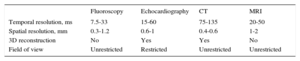
Imaging assessment of the cardiac valves requires high temporal resolution to reduce artifacts caused by cardiac and respiratory motion.29 Technically, the temporal resolution of a moving object can be defined as the minimum separation in time that a technique is able to visualize. Temporal resolution is therefore measured in milliseconds. Table 1 compares the technical characteristics of the main imaging techniques used to assess cardiac valves vs fluoroscopy, which is the leading technique for percutaneous interventions.
Technical Aspects of Imaging Techniques
| Fluoroscopy | Echocardiography | CT | MRI | |
|---|---|---|---|---|
| Temporal resolution, ms | 7.5-33 | 15-60 | 75-135 | 20-50 |
| Spatial resolution, mm | 0.3-1.2 | 0.6-1 | 0.4-0.6 | 1-2 |
| 3D reconstruction | No | Yes | Yes | No |
| Field of view | Unrestricted | Restricted | Unrestricted | Unrestricted |
3D, 3-dimensional; CT, computed tomography; MRI, magnetic resonance imaging.
Echocardiography and cardiac magnetic resonance imaging (cardiac MRI) have a higher temporal resolution than cardiac CT. Data acquisition protocols are the main differentiating factor, because cardiac CT requires a quarter or half gantry spin (depending on whether a single or double X-ray tube is used), while echocardiography and cardiac MRI emit ultrasound or radiofrequency pulses, respectively, to acquire images. Three-dimensional (3D) echocardiography and cardiac MRI can also average different heart cycles to improve temporal resolution.30–36
Spatial resolution is the minimum distance that a technique is able to distinguish as 2 different structures. Again, imaging techniques differ considerably in spatial resolution specifications. The best spatial resolution in echocardiography, for example, is achieved when the measured object is in line with the ultrasound beam, close to the transducer and in the area of maximum focus. Under these optimal conditions, spatial resolution is 0.6-1 mm. In cardiac MRI, cine (balanced steady-state free precession) sequences give a maximum spatial resolution of 1-2 mm, while in cardiac CT the range is 0.4-0.6 mm in all 3 dimensions (giving isotropic data) and does not depend on the area of interest, which is ideal for 3D data reconstruction.29,37
These technical aspects, together with availability and data acquisition time factors, influence the role of different imaging techniques in valve assessment and repair guidance. At present, echocardiography (and fluoroscopy) are the leading imaging techniques in implantation guidance, and cardiac CT is the leading imaging technique in intervention planning.38–41
ECHOCARDIOGRAPHIC-GUIDED PERCUTANEOUS REPAIR FOR MITRAL REGURGITATION: MITRACLIPMitraClip SystemThe surgical leaflet plication described by Alfieri has simplified native valve repair in MR, using a technique that is independent of the regurgitation mechanism itself.42-44 The simplicity and versatility of this technique permit a less invasive approach, initially performed through robotics45 and then percutaneously.
The first percutaneous interventions with the Mobius suture system (Edwards Lifesciences Inc.; Irvine, California, United States)46 were unsuccessful. In 2003, St. Goar et al47 published the first promising results with successful MitraClip deployment in 12 out of 14 pigs. In the 2 remaining animals, the clip detached from one of the leaflets, highlighting the need for echocardiographic monitoring of the grasping step.
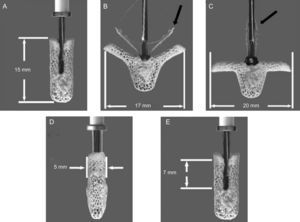
MitraClip (Abbott Vascular; Menlo Park, California) is a triaxial catheter system with an implantable clip at the tip. It consists of a steerable guide catheter and a clip delivery system (CDS) that is advanced through the guide. The CDS can be manipulated on all 3 planes. Finally, the MitraClip device is a 5-mm wide chrome-cobalt clip, with 2 articulated arms that can open to 240°. Inside the clip there is a gripper system to firmly grasp the leaflets and create a double mitral orifice. The outer part of the clip is covered in a polyester mesh. The device can be reopened and repositioned, and multiple clips can be implanted to optimize the result14,48 (Figure 3).
, open at 120° (B) with the grippers partly closed (black arrow), and open at 180° (C) with grippers totally raised (black arrow). The bottom row shows the maximum leaflet length that can be engaged by the clip arms: 5 mm in width and 7 mm in length. Images edited and reproduced with permission of Abbott Vascular.")
MitraClip System. Clip dimensions and movements. Maximum dimensions of the device: closed (A), open at 120° (B) with the grippers partly closed (black arrow), and open at 180° (C) with grippers totally raised (black arrow). The bottom row shows the maximum leaflet length that can be engaged by the clip arms: 5 mm in width and 7 mm in length. Images edited and reproduced with permission of Abbott Vascular.
Due to its anatomical complexity, the MV needs to be studied from different views to construct a study system with 2-dimensional TEE that includes 4 midesophageal views and 1 transgastric view.49 Using a 3D perspective, and drawing on the experience of MitraClip® implantations, this system can be redefined.
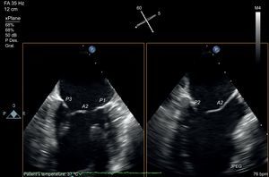
As mentioned above, one of the problems initially faced by pathologists when describing the MV was to define the leaflets, because in fact the MV is a continuous veil-like structure inserted around the mitral annulus, separated by indentations.22 To separate the aortic leaflet from the mural leaflet, pathologists used the commissures as anatomic markers, which, in turn, were identified by the specific CT type (commissural chordae) that inserted into the commissures, aligned by the PMs23 In short, the PMs point toward the commissures (Figure 4), and this reference point marks the long axis of the valve, which is the mitral intercommissural view. Following the Carpentier nomenclature,24 the echocardiographic view shows 3 valve scallops, from medial to lateral: P3-A2-P1. When focused on A2-P2, the orthogonal view to the intercommissural view (with the transducer rotated an additional 90°) typically slices the LV outflow tract (LVOT). By slightly rotating the probe manually toward one and then the other commissure, scallops A3-P3 and A1-P1 can be sliced.
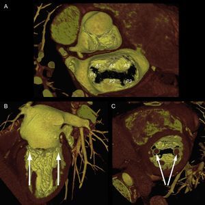
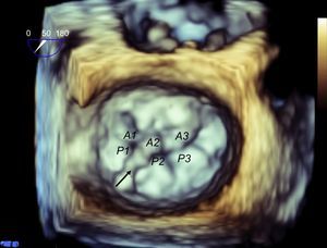
. Longitudinal (B) and transversal (C) views of the ventricle show the papillary muscles aligned toward the commissural zones.")
Mitral valve apparatus on cardiac computed tomography. Volume-rendered 3-dimensional reconstruction showing a mitral valve from a surgical view and leaflet scallops identified according to the Carpentier classification (A). Longitudinal (B) and transversal (C) views of the ventricle show the papillary muscles aligned toward the commissural zones.
The development of matrix-array transducers permits a simultaneous view of 2 orthogonal planes. Using a primary intercommissural view, an orthogonal view along the center shows A2-P2 (Figure 5). If the orthogonal view is rotated laterally toward the lateral scallops, A1-P1 are imaged, and if it is rotated toward the medial segments, A3-P3 are imaged. Finally, to complete the analysis, a 3D view of the valve is obtained (Figure 6). The 3D view improves identification of all the scallops and indentations.
 and the papillary muscle heads. After identifying the long axis of the valve, using the orthogonal view at 90°, the 3-chamber view is found in complete coaxial alignment with the central line of coaptation (A2-P2). The same orthogonal plane is obtained by rotating the plane to 150°.")
Mitral valve analysis with transesophageal echocardiography. Multiplane transesophageal echocardiography image with simultaneous view of two orthogonal planes. Note the intercommissural view on the left, identified by visualization of 3 independent valve scallops (P3-A2-P1) and the papillary muscle heads. After identifying the long axis of the valve, using the orthogonal view at 90°, the 3-chamber view is found in complete coaxial alignment with the central line of coaptation (A2-P2). The same orthogonal plane is obtained by rotating the plane to 150°.

This study protocol, using 3 echocardiographic views (intercommissural, LVOT and 3D), permits an accurate assessment of functional anatomy and the regurgitation site.
Patient SelectionThe first MV anatomic criteria to select candidates for MV repair with the MitraClip system were established in the EVEREST studies48,50,51 (Figure 7). After establishing the safety and feasibility of MitraClip in a phase 1 study,48,50 a pilot study was then conducted, called EVEREST II. In this phase 2 study, 279 surgical candidates with MR were randomized in a 2:1 ratio to undergo percutaneous repair or surgery. The patients treated percutaneously had the following clinical profile: 62% were men, mean age was 67 years, 47% had a history of ischemic heart disease (22% of whom had a previous myocardial infarction), 73% had degenerative MR grade III-IV, 91% had symptomatic heart failure, 34% had atrial fibrillation, 40% were in New York Heart Association (NYHA) functional class II, 45% were in NYHA III, and 60% had preserved LV ejection fraction.51 In real-world practice,16,52–55 this clinical profile has shifted toward treatment of patients who are inoperable, older (mean age 71 years), with functional MR (70% of patients), in NYHA III-IV (90%), and preserved ejection fraction (34%). At 9 months of follow-up, these patients were in NYHA I-II (78% of patients), and with MR grade I-II (89%). During the follow-up period, the mortality rate was 15%.56
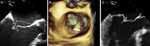
; coaptation length is the zone of leaflet apposition (b). B and C: key anatomic criteria for repairability in degenerative mitral regurgitation due to prolapse or flail shown through 3-dimensional reconstruction (B) and left ventricular outflow tract plane (C); flail width must be < 15 mm (c) and flail height < 10 mm (d).")
Key anatomic criteria for repairability. A: anatomic criteria for repairability in functional mitral regurgitation; coaptation depth measured from the annulus to the free edge of the leaflets must be < 10 mm (a); coaptation length is the zone of leaflet apposition (b). B and C: key anatomic criteria for repairability in degenerative mitral regurgitation due to prolapse or flail shown through 3-dimensional reconstruction (B) and left ventricular outflow tract plane (C); flail width must be < 15 mm (c) and flail height < 10 mm (d).
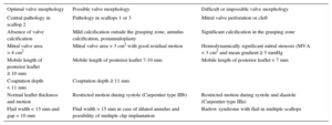
Echocardiographic criteria have also changed. Broader eligibility criteria for MitraClip repair have been applied in view of the positive safety profile of the intervention itself, and the treatment of patients at high surgical risk without other therapeutic options. The successful outcome of the procedure is apparently unaffected by these extended criteria.57,58 Current proposed criteria are based on pooled experience, as published by Boekstegers et al,59 and detailed in Table 2. Criteria for valve repair are subdivided by valve morphology into 3 categories: EVEREST criteria for optimal valve morphology at centers with limited MitraClip repair experience; acceptable valve morphology, reserved for experienced sites; and difficult or impossible valve morphology.
Extended Anatomic Criteria for MitraClip
| Optimal valve morphology | Possible valve morphology | Difficult or impossible valve morphology |
|---|---|---|
| Central pathology in scallop 2 | Pathology in scallops 1 or 3 | Mitral valve perforation or cleft |
| Absence of valve calcification | Mild calcification outside the grasping zone, annulus calcification, postannuloplasty | Significant calcification in the grasping zone |
| Mitral valve area > 4 cm2 | Mitral valve area > 3 cm2 with good residual motion | Hemodynamically significant mitral stenosis (MVA < 3 cm2 and mean gradient ≥ 5 mmHg |
| Mobile length of posterior leaflet ≥ 10 mm | Mobile length of posterior leaflet 7-10 mm | Mobile length of posterior leaflet < 7 mm |
| Coaptation depth < 11 mm | Coaptation depth ≥ 11 mm | |
| Normal leaflet thickness and motion | Restricted motion during systole (Carpentier type IIIb) | Restricted motion during systole and diastole (Carpentier type IIIa) |
| Flail width < 15 mm and gap < 10 mm | Flail width > 15 mm in case of dilated annulus and possibility of multiple clip implantation | Barlow syndrome with flail in multiple scallops |
MVA, mitral valve area.
Echocardiography is an essential technique in MitraClip implantation guidance. At present, these implantations are the interventions that are most dependent on nonfluoroscopic imaging guidance. The implantation procedure is summarized in the steps described below.
Transseptal PunctureThis is a critical step in the procedure and the source of most complications. The triaxial catheter system permits 3-directional movements. The transseptal (TS) puncture is the axis from which all movements are made. By aligning the TS site with the central line of mitral coaptation (A2-P2), more precise movements are achieved along the lateral-medial and anterior-posterior axes of the valve. The distance from the TS site to the leaflet coaptation site should be > 40 mm, and ideally about 45 mm, to permit catheter guide maneuvering in the atrium and to advance the CDS into the LV.
An optimal puncture can be achieved usually in the posterior area of the fossa ovalis. To ensure a successful outcome at this initial stage, the echocardiographer must use a common language with the interventional cardiologist:
- •
The direction in the bicaval view is described as superior-inferior (90°-120°) and it refers to advancing and retracting the TS needle. Superior means cranial movement toward the superior vena cava and inferior refers to caudal movement.
- •
The direction in the great vessel view is described as anterior-posterior (25°-45°) and refers to TS needle rotation. The fluoroscopy marker is usually a pigtail catheter in the aorta. Anterior means rotation toward the aorta and posterior means away from the aorta, toward the posterior atrial wall.
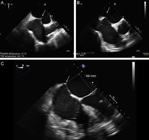
The TS imaging guidance protocol includes 3 TEE views: 2 for positioning (bicaval and short axis views) and 1 for height confirmation (4-chamber view at 0°). It is usually recommended to perform the TS puncture as high as possible in the fossa ovalis in the bicaval view and in the mid-posterior zone in the great vessel view, at a height of about 45 mm (Figure 8).
. B: short axis view of great vessels with posterior puncture (arrow), away from the aorta. C: 4-chamber plane to measure the height from the puncture site to the valve coaptation line, which should be about 45 mm.")
Two-dimensional transesophageal echocardiographic-guided transseptal puncture. A: bicaval view and puncture in the center of the fossa ovalis (arrow). B: short axis view of great vessels with posterior puncture (arrow), away from the aorta. C: 4-chamber plane to measure the height from the puncture site to the valve coaptation line, which should be about 45 mm.
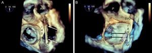
It is generally believed that superior-inferior movement is proportionally reflected in puncture height, ie, if the TS site is at 50 mm, a 5 mm reduction in the bicaval view will lower the TS site to 45 mm. However, this proportionality applies only if the heart is completely vertical, whereas in practice, and especially if there is atrial dilatation, the heart is often in a horizontal position (Figure 9). This is why it may be difficult to locate the puncture site, and cranial-caudal movements may not result in significant changes in height. In these cases, 3D TEE helps clarify catheter behavior and define the puncture site more accurately (Figure 10).
; in the cranial position of the interatrial septum, the catheter is located in the anterior region, whereas in the most caudal position, the catheter is located in the posterior region. B: the same image, shown in 3 dimensions and slightly tilted to show the relation between the fossa ovalis and the mitral coaptation line; note that the cranial-caudal catheter trajectory has little impact on the puncture height (arrows), which depends more on the anterior-posterior position; when the catheter turns toward the aorta, the puncture site is lower, and when it turns away from the aorta, the puncture site is higher. AML, anterior mitral leaflet; Ao, aorta; FO, fossa ovalis; IAS, interatrial septum; IVC, inferior vena cava; PML: posterior mitral leaflet; SVC, superior vena cava.")
Behavior of the transseptal puncture catheter in horizontal hearts. A: relation between structures and the puncture catheter (arrows); in the cranial position of the interatrial septum, the catheter is located in the anterior region, whereas in the most caudal position, the catheter is located in the posterior region. B: the same image, shown in 3 dimensions and slightly tilted to show the relation between the fossa ovalis and the mitral coaptation line; note that the cranial-caudal catheter trajectory has little impact on the puncture height (arrows), which depends more on the anterior-posterior position; when the catheter turns toward the aorta, the puncture site is lower, and when it turns away from the aorta, the puncture site is higher. AML, anterior mitral leaflet; Ao, aorta; FO, fossa ovalis; IAS, interatrial septum; IVC, inferior vena cava; PML: posterior mitral leaflet; SVC, superior vena cava.
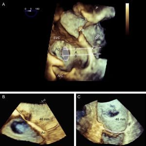
, showing the horizontal heart position and how cranial-caudal catheter movements have little impact on the puncture height above the mitral coaptation line (arrows); therefore, a central puncture can be performed with a bicaval view without affecting height. B: 3-dimensional 4-chamber view; puncture in the most posterior zone of the fossa (away from the aorta) measures about 45 mm in height. C: modified 3-dimensional view with the interatrial septum en face, aligning the mitral annulus to the Z plane; this movement permits more accurate measurements, such that the height from the posterior zone of the fossa to the coaptation line is 46 mm. Combining the data from the 3 images, transseptal puncture can be planned at the center of the fossa ovalis in the bicaval view and in the posterior zone in the great vessel view. This location differs slightly from the superior, posterior puncture that is usually recommended. AML, anterior mitral leaflet; Ao, aorta; FO, fossa ovalis; IAS, interatrial septum; IVC, inferior vena cava; SVC, superior vena cava.")
Preprocedural 3-dimensional planning of the transseptal puncture. Image of 3-dimensional transesophageal echocardiography from a ventricular view (A), showing the horizontal heart position and how cranial-caudal catheter movements have little impact on the puncture height above the mitral coaptation line (arrows); therefore, a central puncture can be performed with a bicaval view without affecting height. B: 3-dimensional 4-chamber view; puncture in the most posterior zone of the fossa (away from the aorta) measures about 45 mm in height. C: modified 3-dimensional view with the interatrial septum en face, aligning the mitral annulus to the Z plane; this movement permits more accurate measurements, such that the height from the posterior zone of the fossa to the coaptation line is 46 mm. Combining the data from the 3 images, transseptal puncture can be planned at the center of the fossa ovalis in the bicaval view and in the posterior zone in the great vessel view. This location differs slightly from the superior, posterior puncture that is usually recommended. AML, anterior mitral leaflet; Ao, aorta; FO, fossa ovalis; IAS, interatrial septum; IVC, inferior vena cava; SVC, superior vena cava.
After the TS puncture has been performed, the catheters are usually exchanged using an extra-stiff Amplatz® guidewire in the left upper pulmonary vein, under fluoroscopic and ultrasound guidance. The steerable guide catheter is advanced, together with a dilator, which can be identified by its tapered tip and echodense markers. The dilator is then withdrawn with the guidewire, and the guide catheter remains in the left atrium. The guide catheter is easily identified by the 2 echodense coils at the tip (Figure 11). The CDS is then introduced through the guide catheter under ultrasound guidance, avoiding atrial wall damage. The steerable guide catheter and CDS must be positioned using a combination of movements to direct the clip tip to the center of the MV, in the direction of the ventricular apex. The clip path is observed on echocardiography, usually via a view with orthogonal intercommissural and LVOT planes.
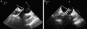
. B: image of the guide catheter after withdrawal of the dilator. Markers denote the guide catheter tip (arrows).")
Transseptal access monitoring. A: transesophageal echocardiographic image showing the dilator crossing the interatrial septum, with echodense markers at the tip (arrow). B: image of the guide catheter after withdrawal of the dilator. Markers denote the guide catheter tip (arrows).
The next step is to align the clip arms with the valve coaptation line by rotating them clockwise and counterclockwise until coaxial alignment is achieved. Three-dimensional TEE and a surgical view are used to position the MV with the aorta at 12 o’clock and the left atrial appendage at 9 o’clock (Figure 12).
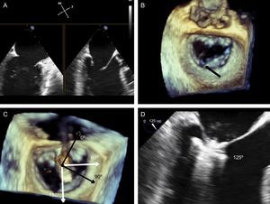
, and therefore the left ventricular outflow tract is at 150°. However, due to the marked indentation separating P1 from P2 (B, arrow), the implantation plane is slightly angulated. To locate the implantation plane, 3-dimensional transesophageal echocardiography must be used to first confirm coaxial alignment with the target zone (C); then the 2-dimensional view must be sought by moving the transducer, to achieve the best view of both open arms (D).")
Implantation plane. The geometry of this mitral valve shows the intercommissural view at 60° (A), and therefore the left ventricular outflow tract is at 150°. However, due to the marked indentation separating P1 from P2 (B, arrow), the implantation plane is slightly angulated. To locate the implantation plane, 3-dimensional transesophageal echocardiography must be used to first confirm coaxial alignment with the target zone (C); then the 2-dimensional view must be sought by moving the transducer, to achieve the best view of both open arms (D).
After checking that the CDS is perpendicular and the clip is aligned coaxially, the system is advanced into the LV. These steps are essential to minimize clip movement in the LV and avoid complications with the CT. In the case of a first clip, the CDS is advanced with the arms open and pointing, usually, toward the center of the regurgitant jet. These steps are monitored with simultaneous orthogonal intercommissural and LVOT planes. It is important to select the best TEE plane for clip deployment monitoring, in the same way that the best fluoroscopic view should be selected in percutaneous aortic device implantation.60 The best plane varies according to the individual patient. If the center of A2-P2 is the planned target site for clip deployment, selecting a good intercommissural plane permits the clip plane to be defined by adding 90° to the intercommissural plane. If the planned target site is elsewhere, after confirming that the system is in coaxial alignment with the valve on 3D TEE, the transesophageal probe and transducer must be positioned around the LVOT plane to provide the best full view of the clip (Figure 12).
Once the clip is inside the ventricle, the main focus is on grasping the leaflets. This process is monitored via an extended view of the implantation plane. Leaflet engagement is achieved by retracting the clip with the arms open, and maneuvering the catheter until the leaflets rest on the arms (Figure 12). When a grasp is obtained, the grippers are lowered, the clip arms are closed and valve function is assessed.
Valve Function AssessmentAssessment of the grasping effect is a key aspect that depends entirely on echocardiography. The assessment covers 3 aspects: reduction of regurgitant jet, degree of stenosis generated, and grasping anatomy.
Residual regurgitation must be assessed under the hemodynamic conditions (blood pressure, vasoactive support) and technical conditions (echographic parameters) that most closely mimic the baseline regurgitation assessment in the catheterization laboratory and under general anesthesia. European and American echocardiography societies have published guidelines on the different criteria for grading MR severity.3,61 While it is beyond the scope of this article to provide an exhaustive analysis of MR grading, we will, however, comment on the limitations of some assessment methods following MitraClip deployment. There is no agreement on how to evaluate residual MR after creation of a double or triple mitral orifice.62 Although a central echocardiographic laboratory analysis found significant changes in regurgitant volume, color flow Doppler, and pulmonary vein flow,63 a recent study has shown poor interobserver agreement and overestimation of residual MR grading by TEE compared with cardiac MRI.64
A multiparametric approach should therefore be used, similar to the approach for native valve assessment,3,61 and taking into account some specific aspects:
- •
Color Doppler jet area assessment overestimates regurgitation grade when multiple jets are involved.65
- •
Mitral E-wave velocity increases in parallel with increased valve stenosis.3,61,66
- •
Quantitation using the Proximal Isovelocity Surface Area (PISA) method is not validated in the presence of more than 1 regurgitant orifice.67
- •
The additive measurement of venas contractas is not validated in the presence of more than 1 regurgitant orifice.
- •
A significant reduction in MR grade is reflected in an immediate hemodynamic change, which can be confirmed by lack of pulmonary vein systolic flow wave reversal, normalized left atrial pressure, increased cardiac output and systolic arterial pressure, and reduced vascular resistance.68
Significant valve stenosis (defined as a mitral valve orifice area < 1.5 cm2) is extremely rare when 1 to 2 clips are implanted, and there is no evidence of progression at 4 years of follow-up.48,69 A faster and more feasible alternative is to perform a mean gradient assessment in the catheterization laboratory. A 5 mmHg cut-off predicts an elevated gradient at discharge.70
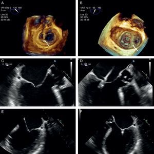
After achieving a satisfactory reduction in MR with the clip, a protocol should be applied to evaluate the anatomy of the tissue surrounding the clip, to reduce the chance of detachment.44,71 This protocol includes an assessment of anterior leaflet motion and interrogation of leaflet insertion in a 0° view, posterior leaflet motion and interrogation of leaflet insertion in the implantation view (usually the LVOT view), and extent of insertion of both leaflets using 3D imaging (Figure 13):
- •
The 0° and LVOT views should show restricted motion of the anterior and posterior leaflets, respectively. The length of inserted leaflet can be measured by slightly rotating the probe manually. The recommended length is ≥ 5 mm, although it may measure up to 7 mm.
- •
A 3D image should show the extent of inserted tissue and formation of 2 pyramids with vertices measuring at least 5 mm, which is the width of the clip. If a large quantity of tissue is engaged in the clip, the pyramid vertices will be wider than the clip itself, probably due to the tension generated.
, with an image of the narrow “pyramid” vertex. B: the clip has detached from the posterior leaflet (asterisk) and a new clip has been deployed medially to the first clip; note the width of the “pyramid” vertex from the new clip (arrow) compared with the first. C-E: length of posterior (C and D) and anterior (E and F) leaflets engaged by the clip, obtained by small panning movements with the probe around the clip.")
Grasping anatomy. The extent of grasping can be analyzed with 3-dimensional transesophageal echocardiography of the mitral valve. A: extent of posterior leaflet insertion is less than the width of the clip (arrow), with an image of the narrow “pyramid” vertex. B: the clip has detached from the posterior leaflet (asterisk) and a new clip has been deployed medially to the first clip; note the width of the “pyramid” vertex from the new clip (arrow) compared with the first. C-E: length of posterior (C and D) and anterior (E and F) leaflets engaged by the clip, obtained by small panning movements with the probe around the clip.
If valve function is deemed satisfactory, the device can be deployed. If it is unsatisfactory, the device can be repositioned. This step should be performed under ultrasound guidance to detect any complications. Increased regurgitant jet is the most common complication, although it has not been reported in the literature. Clip deployment eliminates the support from the CDS and accumulated tension. This changes the relationship of the device with adjacent valve tissue and increases the regurgitant jets on both sides of the clip, due to newly-created commissures.
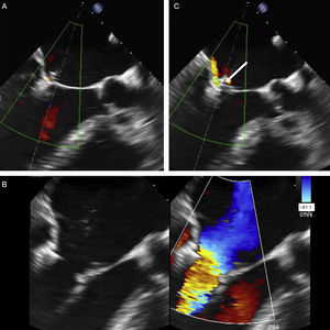
Detachment from a single leaflet is a much-feared but rare complication (Figure 14). Complete clip detachment with embolization has not been reported. Implementation of an implantation analysis protocol has reduced the incidence of single leaflet detachment from 14.3%47 in animal experimentation and 4.8%52 at the start of clinical experience to a current figure of 1.9%.53
, and a regurgitant jet that originates here. Implantation of a first clip hinders the grasping analysis of a second clip.")
Acute detachment of the anterior leaflet. A: both leaflets appear to have engaged well, with reduced leaflet motion. B: however, acute detachment of the anterior leaflet is observed after clip release. C: careful observation of leaflet engagement shows a moving structure above the clip (arrow), and a regurgitant jet that originates here. Implantation of a first clip hinders the grasping analysis of a second clip.
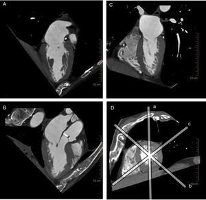
Several factors favor the use of cardiac CT when planning a percutaneous repair for MR, and more specifically, transcatheter mitral valve implantation. There are significant differences between the mitral and aortic valves when planning transcatheter valve implantations: the mitral valve is somewhat calcified, the annulus is larger and has a 3D saddle shape, the subvalvular apparatus is complex, and the LV outflow tract needs to be preserved (Figure 15). This complex anatomy warrants the use of 3D imaging techniques for preprocedural studies,72 and, at present, cardiac CT offers the highest 3D spatial resolution of all techniques.
.")
Multiplane reconstruction in cardiac computed tomography. Note the excellent spatial resolution on all 3 planes, permitting a detailed analysis of the entire mitral valve apparatus. A: vertical longitudinal plane of the heart. B: 3-chamber plane with the left ventricular outflow tract. C: horizontal longitudinal plane of the heart. D: short axis of the heart, sliced by the other 3 planes (a-c).
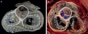
Cardiac CT contributes to transcatheter mitral valve implantation planning in different ways, depending on the implantation site. The Fortis device (Edwards Lifesciences; Irvine, California, United States) is implanted via a transapical approach and is anchored directly on the anterior and posterior leaflets. At the planning stage of this intervention, computed tomography is an adjunct to echocardiography in annulus and leaflet evaluation, and is proving essential in subvalvular apparatus evaluation. Complicated subvalvular anatomy can hinder system advance and device anchoring due to irregular PM branching or fusion, or the presence of prolonged struts or CTs that insert beyond the rough zone of the leaflets.73,74 The Tiara (Neovasc Inc.; Richmond, Canada) transapical mitral prosthesis rests on the atrial surface of the mitral annulus and is anchored on the ventricular surface beside the fibrous trigones and posterior annulus (Figure 16). Cardiac CT has been used for Tiara implantation to achieve a more accurate measurement of the annulus and to plan the best fluoroscopic angulation.41,75,76

Volume-rendered 3-dimensional cardiac computed tomography. Note the relation of the anatomic structures around the fibrous skeleton for preprocedural planning of transcatheter valve implantation. Ao, aorta; L, left fibrous trigone; MV, mitral valve; R, right fibrous trigone; TV, tricuspid valve.
Blanke et al77 published an article with the aim of standardizing the terms that are starting to appear in mitral valve apparatus geometry, and to assess the different imaging techniques used in the planning, intervention, and follow up of transcatheter mitral valve implantation.
Cardiac CT has also been used to plan percutaneous coronary sinus-based indirect annuloplasty for MR, with implantation of the CARILLON system. One of the complications that prevents device implantation is coronary circumflex artery compression. Despite the excellent spatial resolution of cardiac CT in the analysis of coronary venous anatomy78 and adjacent structures, procedural success in the AMADEUS trial79 remained unchanged with advance knowledge of this anatomy.
CONCLUSIONSPercutaneous repair for MR in native valves is an emerging intervention that relies heavily on other imaging techniques beyond fluoroscopy. At present, the main technique for patient selection and intervention guidance is 3D TEE. The technical complexity of percutaneous repair makes specific training in this field absolutely essential for interventional cardiologists and cardiac imaging specialists alike. Additional training in advanced cardiac imaging techniques such as cardiac CT and cardiac MRI is also necessary.
Cardiac CT provides accuracy, reproducibility and a wide field of view in transcatheter aortic valve interventions and similarly in MV repair, by permitting a 3D analysis of the heart and adjacent structures. Considering the complexity of MV anatomy, cardiac CT provides valuable additional information to the restricted field of view of echocardiography, making this technique determinant in the planning and guidance of some percutaneous procedures.
The potential for cardiac MRI lies in the absence of ionizing radiation and its versatility, offering a comprehensive study of anatomy, function, blood flow and tissue characterization. Future improvements in cardiac MRI availability, data acquisition times, and spatial resolution will play a key role in making this technique a strong contender in the field of imaging techniques for percutaneous interventions.
CONFLICTS OF INTERESTC.H. Li and D. Arzamendi are advisers for Abbott and have received nonspecific support for conducting various research projects.
We are grateful to Prof. Alfonso Rodríguez Baeza, Professor of the Department of Morphologic Sciences at the Faculty of Medicine of the UAB (Universitat Autònoma de Barcelona), for answering our questions and for providing the anatomy images published in this article, and to Jorge Carbajo and María Perez at Abbott Vascular, for their assistance and advice in technical aspects. We would also particularly like to thank Nuria López and Martina Li for their patience and support.